 calctric
FREE ONLINE · TWO-BEND OFFSET
From a measurement
to a marked-out plan.
Set your rise, finished length and bender details. Get both marks from START, a layout you can read and a step-by-step sequence.
Your layout will appear here.
YOUR MARKING PLAN
Measure from START.
Finished offset
Before bending · straight pipe
Diagrams show the centreline and marking sequence. The shoe and physical clearances are not depicted.
All layout measurements
ONE STEP AT A TIME
Make your offset.
For a compatible hand bender using the app’s hook-toward-START sequence. Follow your tool’s instructions for support, seating and pressure. This guide does not cover hydraulic or electric machine operation.
WORKED EXAMPLE
A centred 6-inch rise in a 48-inch run.
At 30°, with a 4.625 in radius, 0.706 in outside diameter and a 5 in 90° deduct, the nominal arrow marks are 17.543 in and 29.486 in from START. The starting pipe length is 49.494 in, before adding any fitting or trimming allowance.
To the nearest sixteenth: A = 17 9/16 in, B = 29½ in, starting length = 49½ in. Measure both marks from the same end. Do not add shrink again. Choosing bend-centre references changes the marks to about 18.775 in and 30.718 in; those require a reference calibrated for 30°.
TAKE THE NEXT BEND WITH YOU
See it in 3D.
Take it to the job.
The free Calctric app includes Offset with 2D and 3D views and its build guide. Optional one-time Premium adds rolling offsets, saddles, 90° bends and custom sequences.
Understand the reference.
Why do arrow and centre marks differ?
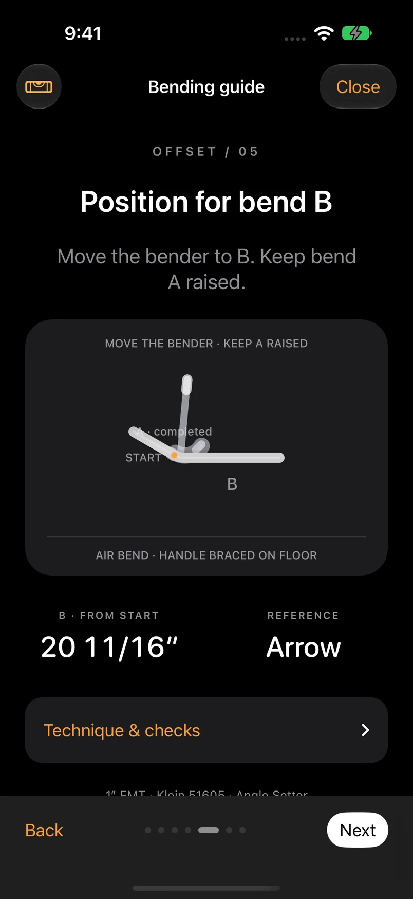
A centre mark identifies the midpoint of the curved section along the unbent conduit. An arrow mark aligns to a different point on the bender. This calculator follows the app’s nominal formula: arrow position = start of the curve + centreline radius + half the conduit outside diameter − 90° deduct. It assumes the hook faces START for both bends.
That formula is a geometric inference, not a field calibration. Confirm it on your shoe. Do not use a 45° or 60° centre notch for a 30° bend. If the correct reference is not available or verified, establish it on test material before using the layout.
Finished length, shrink and cut length
Finished length is the projection along the original run, not the diagonal between pipe ends. Starting pipe length equals finished horizontal length plus geometric shrink. Fitting engagement, cutting tolerance and final trimming are not included.
For rise H, centreline radius R and angle θ in radians, straight S = [H − 2R(1 − cos θ)] ÷ sin θ. Horizontal offset run = 2R sin θ + S cos θ. Developed offset length = 2Rθ + S. Their difference is shrink. This finite-radius method can differ from a point-bend multiplier table.
What still needs checking?
Check conduit/tool compatibility, minimum grip, shoe access, obstruction clearance and the manufacturer’s operating procedure. The geometry does not model springback, material deformation or all physical interference. Enter a verified minimum straight to check all three straight sections against it.
Independently verify the result and applicable local installation requirements. See the terms and safety disclaimer. As a manufacturer reference, the Klein Angle Setter instructions describe tool-specific references and operating methods; their table method is separate from this finite-radius layout.
Where do I measure the two offset marks from?
Measure both A and B along the straight pipe from the same end, labelled START. B is an absolute distance from START, not an extra distance to add after A. The selected mark reference determines what part of the bender you align with each mark.
What does centreline rise mean?
Rise is the distance between the centreline of the starting straight and the centreline of the final straight. It is not an automatic allowance for an obstacle’s height, pipe wall or required clearance. Measure the installation and include the clearance it needs.